Overview - a BLDC controller with stepper motor positioning
This case study describes the design and implementation of a combined brushless DC (BLDC) and stepper motor controller developed for an industrial OEM customer. While the specific customer and end application remain confidential, the project provides a strong example of how system-level thinking and integrated electronics design can deliver significant reductions in product footprint, cost, and assembly complexity.
The core objective of the project was to replace multiple discrete motor control electronics with a single, integrated solution capable of driving both a small BLDC motor and a NEMA 17 stepper motor from a shared 24 V supply. In addition to motor control, the system was required to communicate with the wider machine via CAN bus, aligning with the customer’s existing architecture and future scalability plans.
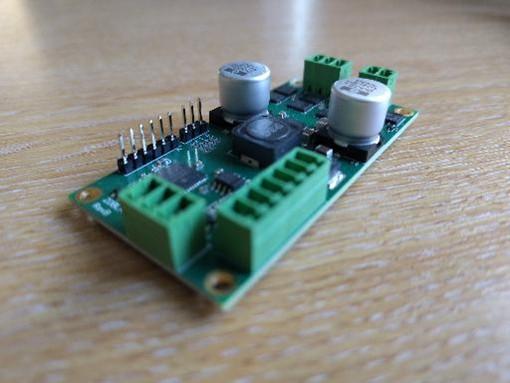
Reduction in Electronics Footprint and Cost Reduction
The customer’s existing product architecture used separate motor controllers for the BLDC motor and the stepper motor, along with additional interface and communication circuitry. This resulted in a relatively large electronics footprint, creating challenges in mechanical packaging and limiting future product revisions.
A key driver for the project was therefore physical integration. By consolidating motor control, power management, and communications into a single controller, the customer aimed to:
- Reduce PCB area and enclosure volume
- Simplify internal wiring and interconnections
- Improve overall product robustness by reducing connectors and cables
The customer also anticipated that a smaller electronics footprint would give greater freedom to their mechanical design team and open up opportunities for product miniaturisation in future variants.
Cost pressure was another major factor. The use of multiple controllers increased the bill of materials (BOM), not only through duplicated components (power supplies, microcontrollers, connectors) but also through higher assembly and test labour.
The integrated controller was expected to deliver cost savings through:
- Reduced component count
- A single PCB assembly instead of multiple boards
- Fewer wiring operations during final assembly
- Simplified end-of-line testing
Crucially, the customer did not want cost savings to come at the expense of performance or reliability. The new controller needed to match or exceed the functional performance of the existing solution while delivering a clear commercial benefit.
System Simplification and Reliability
From a system engineering perspective, the existing multi-controller approach increased the number of potential failure points. Multiple power domains, duplicated interfaces, and inter-board communications added complexity and made fault diagnosis more difficult.
The customer wanted a cleaner system architecture with:
- A single point of control for motion
- Unified fault handling and diagnostics
- Consistent communication with the host system
By consolidating control into one unit, the customer aimed to improve reliability, reduce support issues in the field, and make future software updates easier to manage.
CAN Bus Integration
The customer’s wider system architecture was based around CAN bus, chosen for its robustness, noise immunity, and suitability for distributed control in industrial environments. The new controller therefore needed native CAN bus support, rather than relying on external gateways or protocol converters.
Key CAN-related drivers included:
- Compatibility with the existing machine network
- Deterministic communication for control and status reporting
- Scalable addressing to support future product variants
Technical Requirements
At a high level, the controller was required to support:
· Supply voltage: 24 V DC
· BLDC motor: Small brushless DC motor, up to approximately 5 A
· Stepper motor: NEMA 17 frame size
· Communications: CAN bus
· Form factor: Compact, integrated PCB solution
In addition to basic motion control, the system needed to provide appropriate protection, diagnostics, and fault reporting suitable for an industrial product.
System Architecture
The design began with a top-down system architecture review. Rather than treating the BLDC and stepper controllers as independent subsystems, the project approached them as coordinated elements within a single motion platform.
A shared microcontroller was selected to manage:
- BLDC motor control algorithms
- Stepper motor control and sequencing
- CAN bus communications
- System monitoring and fault handling
This approach avoided unnecessary duplication of processing resources and allowed tighter integration between the two motion axes.
Motor Control Implementation
BLDC Motor Control
The BLDC motor channel was designed to support a small 5 A motor, with efficient switching and precise control. The implementation focused on:
- Reliable commutation across the operating speed range
- Smooth torque delivery
- Robust fault detection for short circuits, overload, and loss of feedback
The controller firmware was structured to allow parameterisation of motor characteristics, supporting production calibration and future motor variants without hardware changes.
Stepper Motor Control
The stepper motor channel was designed around a NEMA 17 motor, commonly used for precise positioning tasks. The controller supported:
· Accurate step generation
· Configurable current control
· Holding torque management to reduce power consumption when stationary
By integrating stepper control into the same platform as the BLDC motor, coordinated motion and unified fault handling became possible.
CAN Bus Communications
CAN bus was implemented as a first-class interface rather than an add-on feature. The firmware architecture defined a clear communication layer responsible for:
· Command reception (e.g. motion requests, configuration updates)
· Status reporting (motor state, faults, diagnostics)
· Error handling and network robustness
This allowed the controller to integrate seamlessly into the customer’s existing system, behaving as a well-defined node on the CAN network.
Conclusion
This project demonstrates the value of integrated motor control design when addressing modern industrial product requirements. By focusing on system-level drivers—footprint, cost, reliability, and communication—the final solution delivered far more than a simple consolidation of electronics.
The combined BLDC and stepper motor controller provided the customer with a robust, scalable platform aligned with their long-term product strategy, illustrating how thoughtful engineering can unlock tangible business value.
Got a similar application? Get in touch to discuss today...